Pages

Sunday, January 25, 2015

MACHIUKA WIFI RADIO PROJECT pag.1

INTRODUCTION


On the mid December 2014 I've decided to make an Internet Radio, because I'd like to listen music permanently, but my old good music starts annoying all my family members, including myself. From years I've listened the same music and... enough is enough. I've started to listen the music on Internet from PC, but it was very uncomfortable. To buy a new WiFi radio was out of question because of price.
Being in the winter holidays times I've decided to make one myself. And so began the journey into the wonderful world of the embedded devices, tiny but strong beauties which bring to me a lot of knowledge that I want to share in this blog.
I had some previous experience on programming, including Arduino stuff, but I'm not a professional. I'm a hobbyst, therefore the programming code that I've made are kept as simple as possible.
The most part of the components are off-the-shelf ones and existing tutorial from the Internet was priceless.
However, the information found on the internet doesn't gave solutions to all the problems encountered, so I had to imagine new solutions. This is why I started this blog. I want it to become a source of inspiration (among others) for everyone who ventures himself into such an undertaking.
The target of this tutorial consisted of peoples which have some knowledge of programming and thinkering. Maybe the solutions provided here are not 100% suitable for the hardware components you have. However, you may find inspiration in the codes that I've provided. I was working only in shell scripts and php. It takes me long hour to solve all the programming problems. For example, only to find how to add two numbers in a shell script was a pain. Unlike the bash (/bin/bash) scripts, the shell scripts (/bin/sh) are relatively very poor documented on the internet. The commands are different. Unfortunately, the bash is not implemented in OpenWrt, only the shell is. I use it because it was convenient to use the UCI capabilities, i.e. to define configuration files in /etc/config/ for keeping the station list and other variables that I need. The second reason is that I was able to send commands to router programmatically.
Finally, I consider it an ongoing process, if my time permitted. Therefore when I'll modify some files I'll updated it. Maybe I'll put the version in the header, in order to not alter or modify the links of downloadings.
Okay, enough chatter! Let's dirt some hands and squeeze some neurons.

PART I - Define the objectives

Our WiFi Radio must have the following capabilities:
  1. Play the internet stations stored into an updatable file from a web interface
  2. Play or stop the desired stations upon a particular schedule (alarm function).
  3. Recording (streaming) stations on demand.
  4. Precise clock (with permanent update from the internet)
  5. Remote control for the usual functions (Play/Stop, Start/Stop Recording, Reboot, Play Favorite Stations, Shuffle Play*)
  6. Volume control
  7. Extra capabilities such as: display currencies rates, current date etc

PART II - Hardware

PART II.a. - Identify the hardware parts


That part my differ, but I describe what I've used for the project
A salvaged satelitte receiver Price : Max $20 ($0 in my case)
TP-Link MR 3020 wifi router with USB portPrice $30
USB sound cardPrice: $7
Arduino Pro Mini - 2 pcsPrice $15 (both)
FTDI USB to Serial breakout boardPrice $6
ENC28J60 Ethernet ModulePrice $7
1 pair of audio mini speakersPrice: $4.5
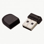
8 GB USB mini stick Price $10
min.5 ports USB hub Price: $4.5
WiFi external antenna (mine is from an old MSI router Price: ?


Saturday, January 24, 2015

MACHIUKA WIFI RADIO PROJECT pag.2

Part II.b. Some technical hints regarding the hardware

Firstly we will speak a little about the Salvaged Satellite Receiver (SSR):
From the picture below you'll notice the main parts of the device:
  1. The power supply
  2. The front panel
  3. The SSR main board
The front panel of this model is a very simple one. It has 3 buttons (unused by me), an IR sensor, a 4 digit 7 elements LED display drived by an ordinary shift register (74 HC 164D) and 2 LEDs. Below you may see it:
Now, the interesting part is. We'll use the 4 digits LEDs to show the current time provided by the router through Arduino. Basically on the router is an application called each minute from crontab which deliver to Arduino the current time. Arduino catch the message and pass it to the front panel shift register to be displayed on the 4 digits 7 elements LEDs.
For this task I've used an Arduino Pro Mini 3,3V with an Ethernet card linked to the router's Ethernet port.
Note: Arduino use two type of Ethernet adapters. One is Ethernet Shield R3 which is used with 'Ethernet.h'library and the other is ENC28J60 Ethernet Module used with 'UIPEthernet.h' which is almost full compatible with 'Ethernet.h' library (in order to run examples written for 'Ethernet.h' you may modify the code line #include "Ethernet.h" with #include "UIPEthernet.h".
For ENC28J60 Ethernet Module there are also other libraries: 'etherShield.h', 'ETHER_28J60.h' (both used by me to receive data from router) and 'EtherCard.h'.
Ironically, with 'etherShield.h' I was able with ease to receive data, but unable to send data to router and with 'EtherCard.h' vice-versa (send data easy, but unable to receive data).
Fortunately, the IR Remote library prevent the proper usage of the shift register and forced me to use another Arduino for the remote control and another way to transfer the remote control codes (TP-LINK MR 3020 has only one single Ethernet port).
As you may see from the pictures below, Ethernet Shield R3 is bulky and expensive ($30-$35) and in conclusion ENC28J60 Ethernet Module is the most suitable for our project
Ethernet Shield R3ENC28J60 Ethernet Module

Friday, January 23, 2015

MACHIUKA WIFI RADIO PROJECT pag.3

Part II.b. Some technical hints regarding the hardware (cont.)

As I said, for sending remote control codes from Arduino to router I used the serial transmission via USB.
In order to do that I use another Arduino Pro Mini (I have a 5V one) with a FTDI basic breakout board (I have a 3,3V one).
Fortunately the pair FTDI 3,3V - Arduino Pro Mini 5V works flawlessly.
Below I'll show you the wiring diagram between the two.
FTDI board 3,3VArduino Pro Mini 5V
GNDRAW
CTSGND
3V3Vcc
TX0RX0
RX0TXO
DTRDTR
And voila' the lovely pair
Note:You may load also the sketch from computer into Arduino Pro Mini 5V with the 3,3V FTDI BASIC breakout board. I notice also that the 5V version of Arduino Pro Mini is cheaper than the 3.3 V version.
Now follows one of the most delicate part of our project: to fix an external antenna (pigtail) to our little MR 3020 router. You need that because when you put the cover on the SSR case you lose the WiFi signal. Another way could be to cut the lid of the SSR case and to insert the router from above.
Attaching a pigtail to 3020 router is described here: How to connect a pitgail to a MR 3020 router

I've sacrificed an old MSI router with an external antenna. To open the case of the MR 3020 router is relatively easy. See the instructions here:Opening the case of a MR 3020 router.
My final result could be observed in the pictures below. You could also notice in the left side of the antenna the speaker's potentiometer.

Thursday, January 22, 2015

MACHIUKA WIFI RADIO PROJECT pag.4

Part III - THE SOFTWARE

Briefly the main steps to be followed are:
  1. Install OpenWrt
  2. Configure the network settings
  3. Extend the router memory by configuring an USB pendrive (even 4 GB pendrive is OK)
  4. Install serial communication drivers
  5. Install sound related drivers/applications. I use madplay, because is frugal, i.e. consume few resources.
  6. Put in place the custom made application
  7. Test the result, using the web interface
Note: All the needed software is provided in this blog
The steps 1,2 and 4 are fully described in my youtube tutorial, but there are also other places on the internet to find it described.
Those steps are enough to have a cheap WiFi radio and, as a bonus, a WiFi signal extender.
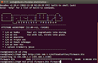
So, in order to install OpenWrt you need the image to be flashed. You may download one from here
Briefly, the MR3020 router installation process is presented below:
1. Install OpenWrt:
2.Configure the network settings.
On your computer, in Terminal or Putty type: telnet 192.168.1.1. Will be appear to you the OpenWrt screen: .
Then type passwd and put a password. Type exit to close the telnet connection. Now you may be able to connect with your beloved router with SSH. On your PC terminal type ssh root@192.168.1.1 and lo and behold, you're connected via SSH.
There are 3 files in OpenWrt that must be replaced or modified: /etc/config/network (do not forget to note the MAC Address prior to replace it), /etc/config/wireless and /etc/config/firewall.
3.Extend the router memory by configuring an USB pendrive:
First of all you must prepare an USB pendisk by having on it 3 partitions: one EXT4 (1-2GB for the operating system), one FAT (for streaming radio station) and one Linux SWAP (approx: 100 MB). There are a bunch of tutorials on how to do that.
Power off the router, put the USB pendrive in it, put also the USB sound card and power on the router(use the USB hub to connect all the stuff).
On the router prompt type the following commands: opkg update, opkg install kmod-usb-storage, opkg install kmod-fs-ext4 block-mount, opkg install fdisk. Then type fdisk -l to see the EXT4 partition name. Could be sda1, or sda3.
Now type: mkdir -p /mnt/sda1 or sda3 (see the previous command fdisk -l output.
mount /dev/sda1 /mnt/sda1, then type mkdir -p /tmp/cproot, mount --bind / /tmp/cproot
tar -C /tmp/cproot -cvf - . | tar -C /mnt/sda1 -xf -, umount /tmp/cproot, umount /mnt/sda1
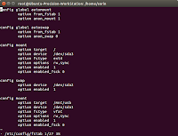
Now edit the fstab file, as follows: vi /etc/config/fstab and modify it as is shown in the picture below:
Save and exit the fstab file (ESC wq) and type reboot in order to reboot your little router.
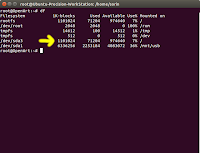
When the router is back to business log in with SSH and type df command. You must see something like that:
Incidentally you may encounter an error that contained the following: whole_root-disabled. If it happened, type: cp /.extroot.md5sum /tmp/whole_root-disabled/etc/extroot.md5sum.
As you maybe seen from the last picture, I have also a partition named "USB". It is the FAT partition that I've made for the streaming files.
To make one, type: opkg update, opkg install kmod-fs-ext4 kmod-fs-vfat kmod-nls-cp437 kmod-nls-iso8859-1
mkdir -p /mnt/usb, mount -t vfat /dev/sda1 /mnt/usb. Basically I've created a folder in /mnt/usb where will be stored the streaming files.
4.Install serial communication drivers
Few considerations about serial communication: We need the serial communication for connecting Arduino to USB.
From my experience, OpenWrt see an Arduino UNO as /ttyACM0 and Arduino Pro Mini, connected through FTDI BASIC outbreak board as /ttyUSB0.
Pay attention then, when you test your Arduino-router communication, to rename the commands you give accordingly (i.e. ttyACM0, or ttyUSB0).
Now, there are three types of TTL to USB devices, FDTI BASIC outbreak board been one of them; another one is a cheap and bulky one based on PL2303 chip and the third one is a little more expensive, but smaller one, based on CP2102 chip.
You must verify of what type is yours, in order to know what applications must be installed on OpenWrt.
Now, you need to type: opkg update, opkg install kmod-usb-acm needed when you test the application with your Arduino UNO
And now, depending your USB to serial breakout board (FTDI BASIC, PL2303 or CP2102), you'll install one of the following:
  • opkg install kmod-usb-serial-ftdi
  • opkg install kmod-usb-serial-pl2303
  • opkg install kmod-usb-serial-cp210x

You may need even opkg install coreutils-stty.
It is helpful to change the baud rate, but I've noticed that ttyACM0 and ttyUSB0 are working on 9600 bps. Anyway, if you need to change the baud rate, just type: stty -F /dev/ttyACM0 9600 clocal cread cs8 -cstopb -parenb . The command is self explanatory.
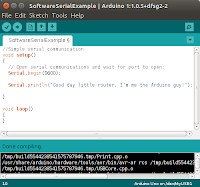
Now, to test the communication between Arduino and router, link the two devices via USB cable, upload a simple sketch into Arduino and
catch the message on router side.
I've made a simple sketch based on SoftwareSerialExample
Now, on router type: cat /dev/ttyACM0 or cat /dev/ttyUSB0, depending on your board (Arduino UNO, or Pro Mini).
If the message appear, you're on track. Well done!
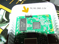
Remember, you need only one way communication through serial: from Arduino to MR3020 router, in order to transmit IR codes from remote control. NoteThere are also a serial connection on router main board; it is the UART connection ttyATH0. See the picture below. But in order to access that serial console you need to rebuild the flash image for OpenWrt. That's beyond the goal of my tutorial.

Wednesday, January 21, 2015

MACHIUKA WIFI RADIO PROJECT pag.5

Part III - THE SOFTWARE - cont

5.Install sound related drivers/applications
Now, as I said, we'll use madplay for playing audio streaming from radio stations, because is less resource consumming than mpd. On my initial stages I've installed mpd & mpc, but I give up. The sound was horrible (because it forced the limits of the router I guess). I spent almost half a day at the time, but of no use. It was easier for me to make a web interface for madplay than to configure mpd to act properly on my router.
For the recording feature, I've installed streamripper application, a very good one.
The commands are:
  • opkg update
  • opkg install kmod-usb-audio
  • opkg install madplay
  • opkg install streamripper
  • opkg install wget
Power off the router, connect the USB sound card to the speakers, power on the router and test madplay.
wget -O - http://205.164.62.15:9010/ | madplay -
Pay attention that is wget -O, not wget -0 (zero)
Now you must be able to hear the sound of music in your speakers.
6.Put in place the custom made applications
To obtain the best results of our WiFi Radio, we need some custom made applications
There are some on the router side and a couple of others one the Arduino side, as follows:
ON THE ROUTER SIDE
Name of the applicationPathDescription
a.The web interface files
play.cgi/www/cgi-bin/nmsradio/the main web interface for controlling our WIFi radio. A short presentation could be seen on youtube
changechannel.sh/www/cgi-bin/nmsradio/changing the radio stations through the command received from play.cgi
alarm.cgi/www/cgi-bin/nmsradio/web interface for setting the alarms
setalarm.sh/www/cgi-bin/nmsradio/setting the alarms according to the parameters received from alarm.cgi
record.sh/www/cgi-bin/nmsradio/stream the content of the current playing radio station on a location on USB disk
b.The Arduino interface files
interfata.sh/www/cgi-bin/nmsradio/It's similar to play.cgi, only it interpret the IR codes received from Arduino
radioIR/etc/init.d/Start at boot the interfata.sh file
ceasArduino.sh/root/scripts/Send to Arduino, via Ethernet, the current time (it runs in crontab every minute)
metals.php/www/php/Send the silver quotation to Arduino. It's called from interfata.sh when a dedicated remote control button is pressed
valuta.php and cursValutar.php/www/php/Send some currency quotation from Romanian National Bank to Arduino. It's called from interfata.sh when dedicated remote control buttons are pressed
c.The common files
radio/etc/config/Store the variables used by applications (ex. current station, current volume, etc.)
posturi/etc/config/Store the radio station list. It could be modified in order to put or delete stations.

Note:All the files with the .cgi or .sh extensions must be executables. In order to do that you must type:chmod +x /pathToFile/filename.ext. Where filename.ext is the name of the file (ex. play.cgi). Also radioIR file must be executable.
If you want to use php files you need to install php to your router:
  • opkg update
  • opkg install php5
  • opkg install curl
  • opkg install php5-mod-curl
  • opkg install php5-fastcgi
  • opkg install php5-mod-json
ON THE ARDUINO SIDE
Name of the applicationDescription
a.Arduino Pro Mini with ENC28J60 Ethernet Module
EthernetReceiveData.inoDisplay on the 4 digits 7 elements LED the 4 numbers received from router
b.Arduino Pro Mini with USB to serial breakout board
IRSendingCodes.inoSend to the router the remote control codes when a button is pressed

Note:
  • Depend on your remote control, the codes may vary. Modify it accordingly.
  • The IP address of my router is 192.168.0.67
  • The IP address of Arduino Pro Mini is 192.168.0.15

For your convenience, you may download all the files from HERE

MACHIUKA WIFI RADIO PROJECT pag.6

Part IV - PUT EVERYTHING IN PLACE

We've arrived at the finish line, i.e. to put everything together in the donor case of Salvaged Satellite Receiver (SSR).
The steps are:
  1. Put in place the WiFi radio hardware components
  2. Test the result, using the remote control
Put in place the WiFi radio hardware components.
Briefly, our inventory consist of:
  1. Salvaged Satellite Receiver
  2. Power supply of the SSR
  3. Front panel of the SSR
  4. MR3020 router with external antenna
  5. Arduino Pro Mini + ENC28J60 Ethernet Module+ Ethernet cable (the one provided with the router)
  6. Arduino Pro Mini + USB to serial breakout board
  7. USB hub with enough ports for all the stuff
  8. USB pendrive of minimum 4 GB
  9. Salvaged remote control
  10. USB powered speakers
  11. USB cables

My setup is presented in the picture below:

I know, it look a little messy, but forgive me, that's my first prototype. Maybe the second will be a good looking one.
The final result instead look very stylish ( I think).
Test the result, using the remote control.
The youtube video clip that I made show the final tests.
ENJOY YOUR STATE-OF-THE-ART WIFI RADIO !.